PC application - Some code to start
For those who want to develop a PC application to configure the gyro.
Remember: This is only possible with the bootloader running!
/* Configuration */
typedef struct _config_
{
uint8_t version;
uint8_t mark[3];
uint16_t servo_freq; //not used
uint16_t hi_endpoint; // [1600..2100]
uint16_t low_endpoint; //[900..1400]
uint16_t midpoint; //not used
uint8_t reverse; // [0..1]
uint8_t rudder_deadband;// [1..100]
uint8_t rudder_speed; // [1..8]
uint8_t delay_cw; // [1..8]
uint8_t delay_ccw; // [1..8]
uint8_t rudder_delay; // [1..8]
uint8_t servo_speed; // [1..140] ms
uint8_t kP; // [1..128]
uint8_t kI; // [1..128]
uint8_t kD; // [1..128]
} config_t;
int enter_gyro(void)
{
SerialWrite(0x1B);
delay_ms(500);
SerialFlush();
SerialWrite('7');
if(SerialRead(200) == '?')
return 1;
return 0;
}
int read_gyro( uint16_t address, uint8_t *buf, uint16_t size)
{
if(!enter_gyro())
return 0;
SerialFlush();
SerialWrite('P'); // Enter Prog Mode
if(SerialRead(1000) != 0x0D) return 0;
SerialWrite('A'); // Set Address
_delay_ms(1);
SerialWrite(address>>8);
_delay_ms(1);
SerialWrite(address&0xFF);
if(SerialRead(1000) != 0x0D) return 0;
while(size--)
{
SerialWrite('d'); // Read Data Memory
*buf++ = SerialRead(1000);
}
SerialWrite('L'); // Leave Prog Mode
if(SerialRead(1000) != 0x0D) return 0;
return 1;
}
int write_gyro( uint16_t address, uint8_t *buf, uint16_t size)
{
SerialFlush();
SerialWrite('P'); // Enter Prog Mode
if(SerialRead(1000) != 0x0D) return 0;
SerialWrite('A'); // Set Address
_delay_ms(1);
SerialWrite(address>>8);
_delay_ms(1);
SerialWrite(address&0xFF);
if(SerialRead(1000) != 0x0D) return 0;
while(size--)
{
SerialWrite('D'); // Write Data Memory
_delay_ms(1);
SerialWrite(*buf++);
if(SerialRead(1000) != 0x0D) return 0;
}
SerialWrite('L'); // Leave Prog Mode
if(SerialRead(1000) != 0x0D) return 0;
return 1;
}
void main(void)
{
read_gyro( 6, (uint8_t *) &gyro_config, sizeof(config_t));
................
write_gyro( 6, (uint8_t *) &gyro_config, sizeof(config_t));
}
Sunday, November 6, 2011
The 0.04 Beta Application
Here is one more version!
You can place the gyro face up or down (the delay cw and the delay ccw will be swapped).
Increase the RudderDelay only if you get bounce with maximum values on Delay CW and CCW.
The servo frequency is fixed to 250Hz but you can change it on the code and compile again.
Please let me know your results here or on the discussion thread .
Parameters you can now adjust with transmitter:
Direction - LED - 1 blue, [1..2] red
EndPoint1- LED - 2 blue, 1 red
EndPoint2- LED - 3 blue, 1 red
RudderSpeed - LED - 4 blue, [1..8] red
Delay CW- LED - 5 blue, [1..8] red
Delay CCW- LED - 6 blue, [1..8] red
RudderDelay - LED - 7 blue, [1..8] red
Parameters possible to adjust with PC program or Program Box (to be done):
Rudder Deadband, Servo Speed, kP, kI and kD.
Download it!
Saturday, October 8, 2011
The 0.03 Beta Application
No bounce!
With this version place the gyro face up.
All configurable parameters are the same on the previous version.
Download it!
Debug version here.
No bounce!
With this version place the gyro face up.
All configurable parameters are the same on the previous version.
Download it!
Debug version here.
Saturday, September 10, 2011
The 0.02 Beta Application
Here is the second release! With a 72% gain in my Tx I got a good results and just a small bounce on clockwise stops. The tail speed is now controlled and it's proportional to the rudder stick position. The servo frequency is fixed to 250Hz but you can change it on the code and compile again. Maybe next versions it will be configurable.
You can find a discussion thread here.
Parameters you can now adjust with transmitter:
Direction - LED - 1 blue, [1..2] red
EndPoint1- LED - 2 blue, 1 red
EndPoint2- LED - 3 blue, 1 red
RudderSpeed - LED - 4 blue, [1..8] red
Delay - LED - 5 blue, [1..8] red
Enter prog mode: rudder stick for one side and pulse 3 or 4 times the gyro switch on the tx.
Change item with the gyro switch.
End prog mod: pulse 3 or 4 times the gyro switch on the tx. You must do it to save the changes!
There are also ServoSpeed [1..140] ms, default value is 70ms and it's not possible to change it with the transmitter. It will be changeable by a PC application or a prog box.
Download and try it!
Here is a version for debug. The gain is fixed in the code so you can keep the gain connector connected to your PC. Now you can see debug information on the TeraTerm and change several parameters with the PC keyboard.
Download and debug it!
Some data logs I got. Rudder Command, Tail Speed and Pid Error


Saturday, August 20, 2011
The 0.01 Beta Application
This is the first version. It supports rate mode and Heading Hold mode. It´s working quite well but we have to adjust better the PID parameters. I did the tests with a HBKing II with a 450 tail on a "lazy susan". Now I'm waiting for a bluetooth device to connect it to the gyro so I will be able to send data to the PC in real time without cables connected to the Heli. My radio is a Spektrum Dx6i and currently I have 25% for rate mode and 62% for HH mode.
Later I will explain better the code...
Download and try it!
Here is a version for debug. The gain is fixed in the code so you can keep the gain connector connected to you PC and sending debug information like sensor values to the TeraTerm.
Download and debug it!
Compile and Load the Application
In order to compile the application you need to install the WinAvr.
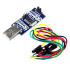
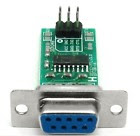
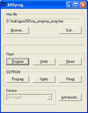
Once you have the .hex file you can load it on the gyro with the AVRprog tool (V1.37) and this hardware connected between the gain connector and a device that provides rx/tx TTL (5V) levels from your PC. You can find devices for USB or Serial port on Ebay.
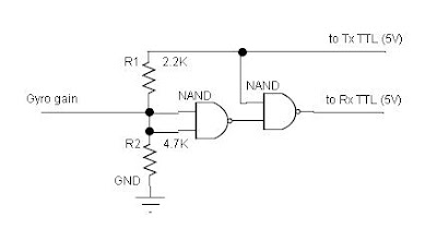
(If your Tx level is 3.3V skip the R2 resistor)
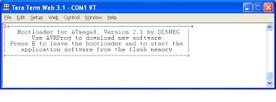
Run a terminal program like TeraTerm baud 19200 8N1. Power the gyro (gain connector), the red led will flash, send an ESC key and the red led will go solid.
Close the TeraTerm and run the AVRprog, select the .hex file and program the flash.
Power down the gyro or send an 'E' with Teraterm and that's all! You have your application ready to run!
After power on the gyro will stay ~4 seconds in the bootloader red led flashing waiting for an ESC then the Application will run!
My stuff:

In order to compile the application you need to install the WinAvr.
Once you have the .hex file you can load it on the gyro with the AVRprog tool (V1.37) and this hardware connected between the gain connector and a device that provides rx/tx TTL (5V) levels from your PC. You can find devices for USB or Serial port on Ebay.


(If your Tx level is 3.3V skip the R2 resistor)
Run a terminal program like TeraTerm baud 19200 8N1. Power the gyro (gain connector), the red led will flash, send an ESC key and the red led will go solid.

Close the TeraTerm and run the AVRprog, select the .hex file and program the flash.

Power down the gyro or send an 'E' with Teraterm and that's all! You have your application ready to run!
After power on the gyro will stay ~4 seconds in the bootloader red led flashing waiting for an ESC then the Application will run!
My stuff:

Thursday, August 18, 2011
Load the BootLoader
The goal is to load the application and configuration through the gain connector without any hardware mods. For that you need to program the a ATmega8 with a BootLoader to be able to communicate by a single wire (the signal wire on the gain connector).
I´ve used the DL5NEG bootloader slightly modified for this purpose.
Download the bootloader code and the hex file.
To program the ATmega8 you need a programmer device like the AVRISP mkII or use the PonyProg and the PC parallel port with some extra hardware.
Open the gyro and connect the programmer to the SPI interface (VCC, GND, MOSI, MISO, RESET and SCK) . See the pcb pictures and use your iron solder carefully.
Once the bootloader is programmed set the fuse bits like this:

Now you can remove all the wires that you have soldered and close the gyro!
Subscribe to:
Posts (Atom)